
Bridging the gap between design and production
In engineering and manufacturing, a design must be more than visually correct. Relationships between parts, materials, dimensions, and manufacturing constraints need to remain consistent in the same model.
Transferring design data to production without reinterpretation is a complex engineering problem involving CNC machines, tool geometry, machining faces, and safe cutting scenarios.
A connected production workflow between CAD and CAM
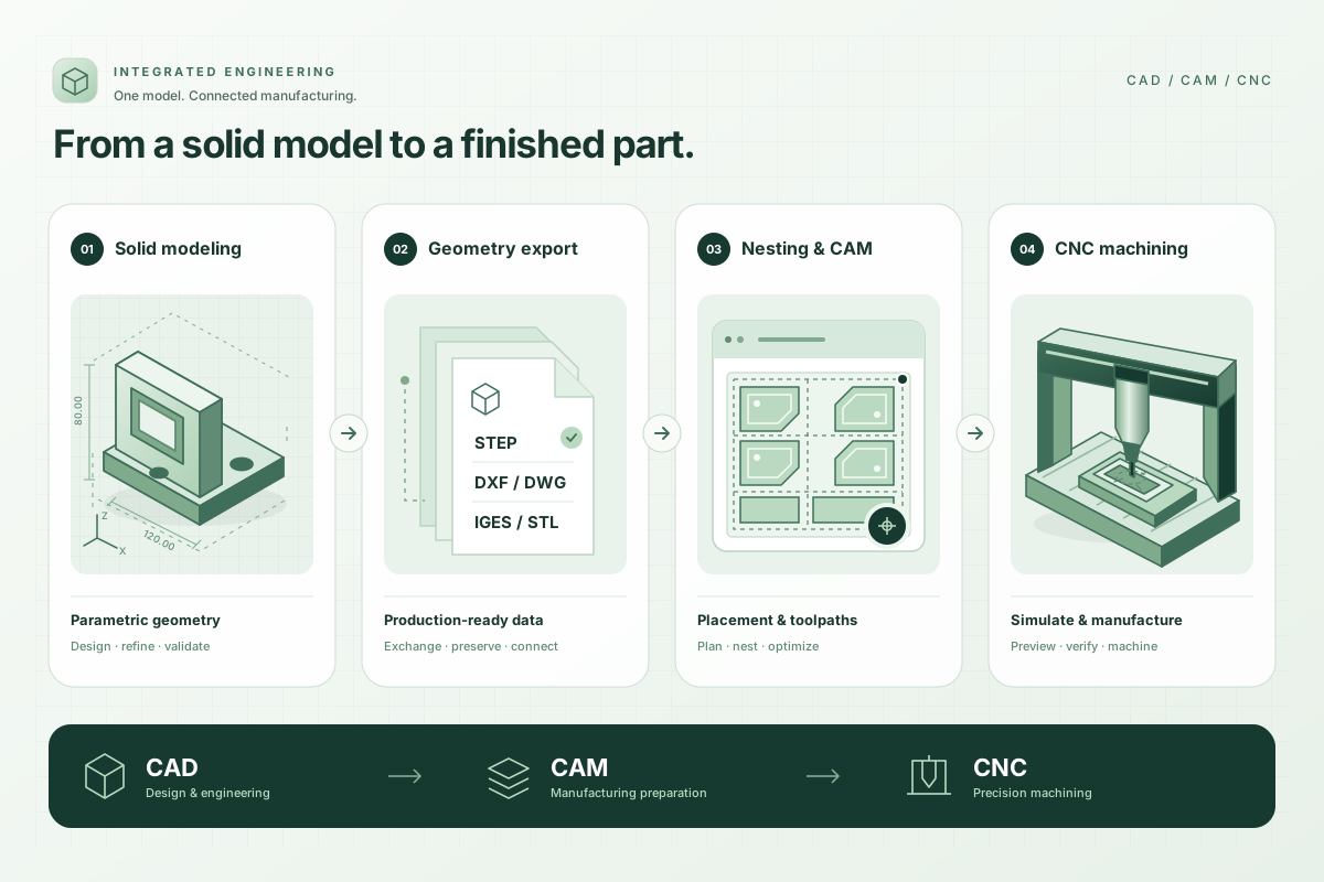
The CAD application combines design, manufacturing-data preparation, and reporting. Prepared data passes to the CAM application, connecting design with manufacturing preparation.
The CAM application turns that data into machine-specific production output. Our team developed these applications end to end, with use in real production.
What it enables
Data prepared during design becomes production output in the CAM application. Design and machine preparation operate as connected steps in the workflow.
Manufacturing-data preparation and reporting support sharing design information with production teams and enterprise systems.
Core capabilities
Parametric 2D/3D modelling
Reusable design infrastructure where parts respond to dimensions and relationships.
Design validation
Rules that identify geometry, placement, collision, and manufacturability risks during design.
Manufacturing data and interoperability
DXF/DWG-based import, export, and reporting flows that preserve part, material, and machining information.
CAM and cutting simulation
Part nesting, toolpath generation, machining-step visualization, and simulation before production.
Technical scope
- .NET and C#
- WPF desktop architecture
- 3D solid geometry viewer
- 2D/3D geometry processing
- DXF/DWG processing
- CNC code, toolpaths, and cutting simulation